


 西门子官方商城
- {{item.name}}
更多

PLCSIM Coupling 信号仿真

发布时间:2024年08月22日
- 0
- 259
本章节介绍了SIMIT软件进行PLC SIM接口的仿真
组态PLCSIM Coupling 信号仿真
1、 PCS7 导出符号表
SIMIT 提供PLCSIM Coupling 导入向导功能,可以把 AS 程序导出的符号表进
行导入,下面介绍下通过AS 程序导入的过程:
1)打开AS 程序中的符号表;
2)按地址对符号表进行排序;
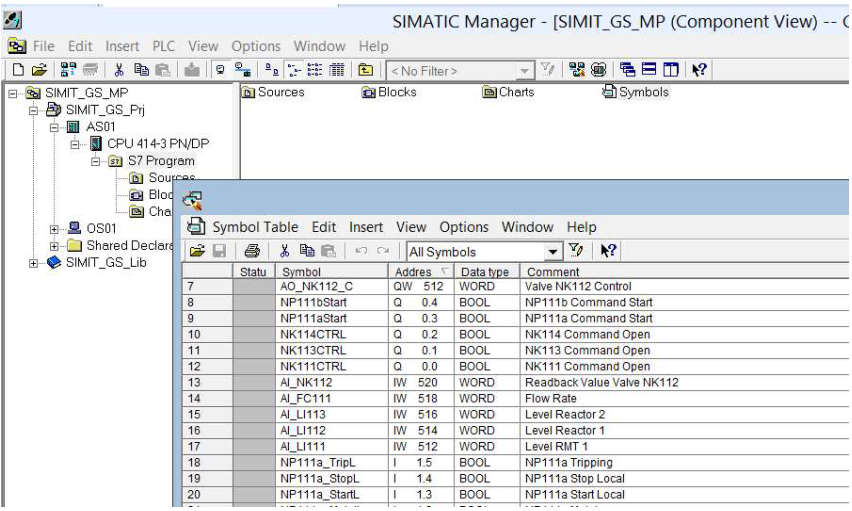
图 5-1 PCS7 符号表
3)标记所有输入输出地址;
4)导出符号表“Symbol Table>Export”。
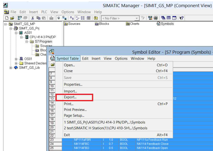
图 5-2 符号表导出
2 、配置PLC SIM Coupling
1) 切换到SIMIT 项目视图;
2)打开“Couplings”文件夹,双击“New coupling”(下图①所示);
3)在对话框选择“PLCSIM”;
4)修改coupling 名称“AS01”(下图②所示);
5)双击“Coupling”打开工作区域;
6)通过“SIMIT_GS_Symbols.asc”导入输入输出信号(下图③所示);
7)选择“New singnals”导入过程开始(下图④所示)。
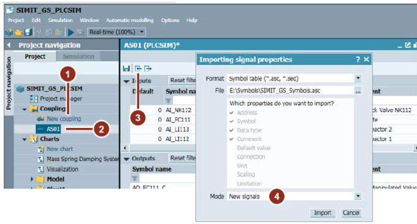
图 5-3 符号表导入
3、PLCSIM Coupling 信号仿真
1)点击SIMIT 运行按钮( )开始仿真,前提条件是PLCSIM 已经运行,否则系统会有报错信息;
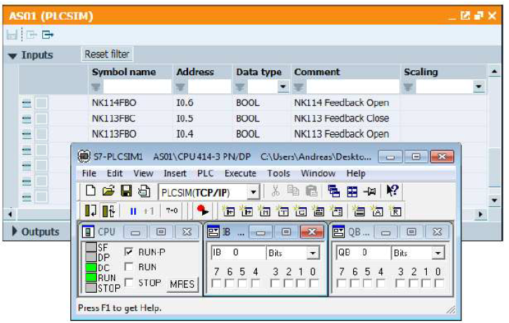
图 5-4 运行PLCSIM 信号仿真
2)需要激活信号隔离器(下图①所示)才可以对信号进行手动操作;
3)通过转换按钮(下图②所示)激活一个开关量信号,例如“NK113FBO”地址为“I0.4”;
4)如果PLCSIM 输入变量正在运行,则“IB 0 Signal 4”显示对应的状态值(下图③所示)。
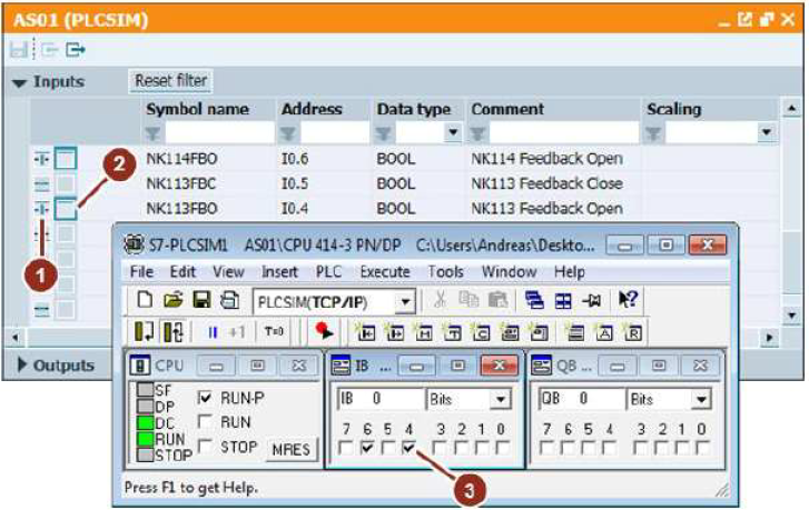
图 5-5 仿真运行结果

- 评论
更多
-
分享
扫码分享
- 收藏 收藏
- 点赞 点赞
- 纠错 纠错


{{item.nickName}}