西门子北京技术支持:
在调试ASIC SIM1-2芯片时,按照规格书上面的推荐电路做出了个PCBA(装配完毕的PCB)。在下图中的Profibus-PA两端给芯片上电DC20V,不工作 -- VREG处无3~5V的电压输出!!!
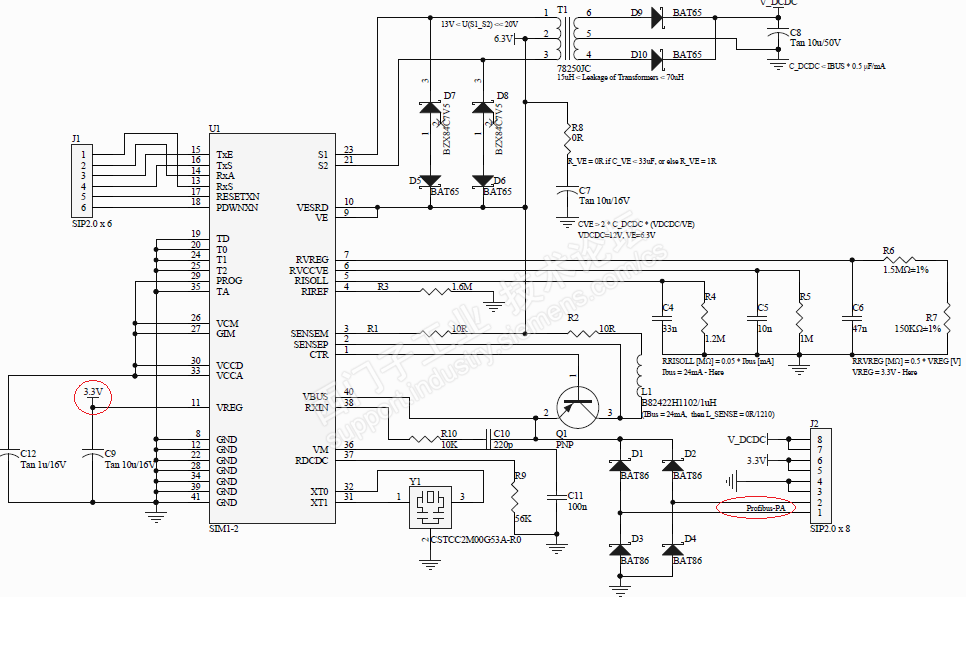
规格书上面的图片如下:

不过从SIM1-2的规格书上面有一段这样的话:
2.3.1 Interfacing with the Bus Cable: VBUS and GND
The interfacing to the positive side of the bus system is over VBUS. Externally, at
least one diode must be included as polarity reversal protection to avoid both
destruction of the ASIC and return feed to the bus cable if a short-circuit occurs.
The interfacing to the negative side of the bus system is over GND.
As an alternative to a diode as polarity reversal protection, a rectifier
bridge can be used as polarity reversal protection and feedback protection.
也就是说电源正通过至少一个二极管后接到VBUS脚,电源负接GND。那么这个电源负到底是接GND还是按照上面图片红色圈里面的Profibus-PA总线接呢?至少现在接Profibus-PA总线的接法不见芯片工作(但愿我哪里搞错了)。
刚才尝试将电源正接Profibus-PA总线的任意端,电源负接GND时,看见电源适配器过流现象
- 电压瞬间被拉低到9V,过流指示红灯亮了。不知道芯片是否被烧掉?169元哦。
换回到电源正负接Profibus-PA总线两端的情况,测量了一下GND与Profibus-PA两总线之间的电压,一个是-23V,一个是-6V。还真是越忙越乱了的。


 西门子商城
西门子商城 西门子中国
西门子中国


 普通
普通


 本版热门话题

 相关推荐
相关推荐 相关帖子推荐